How Brake Systems Work

How Brake Systems Work: In-Depth Technical and Physical Analysis
Automev.Com Blog Post
Brake systems are among the most critical components for ensuring vehicle safety, combining advanced engineering principles with fundamental physics. In this article, we’ll explore the entire process, from the driver pressing the brake pedal to the vehicle coming to a complete stop. We’ll cover the detailed operation of brake systems, their technical aspects, and the underlying physical principles that govern them.
1. How Human Force is Transformed into Mechanical Action
1.1 Brake Pedal and Force Amplification
The braking process begins when the driver applies force to the brake pedal. The pedal functions as a lever, amplifying the force and transmitting it to the braking system.
Physical Principle:
Force amplification in a lever is calculated as:
Foutput=Finput×LoutputLinputF_{\text{output}} = F_{\text{input}} \times \frac{L_{\text{output}}}{L_{\text{input}}}Foutput=Finput×LinputLoutput
Where:
- FoutputF_{\text{output}}Foutput: Force transmitted to the brake master cylinder
- FinputF_{\text{input}}Finput: Force applied by the driver
- LoutputL_{\text{output}}Loutput: Length of the pedal arm’s longer section
- LinputL_{\text{input}}Linput: Length of the shorter section
This design increases the driver’s force by 4–10 times.
2. From Force to Pressure: Hydraulic and Air Systems
2.1 Hydraulic Systems and Pascal's Principle
In hydraulic systems, the force applied by the driver is transferred to the master cylinder, compressing hydraulic fluid to generate pressure.
Pascal's Principle:
In a closed fluid system, pressure applied at any point is transmitted equally throughout:
P=FAP = \frac{F}{A}P=AF
Where:
- PPP: Hydraulic system pressure
- FFF: Force applied
- AAA: Surface area of the piston
This ensures equal braking pressure is distributed to all wheels.
2.2 Air Systems and Thermodynamic Principles
Air brake systems rely on compressed air, generated by a compressor and stored in reservoirs. When the brake pedal is pressed, the compressed air is released to the brake actuators.
Boyle's Law:
At constant temperature, the pressure and volume of a gas have an inverse relationship:
P1×V1=P2×V2P_1 \times V_1 = P_2 \times V_2P1×V1=P2×V2
Where:
- P1,V1P_1, V_1P1,V1: Initial pressure and volume
- P2,V2P_2, V_2P2,V2: Final pressure and volume
Compressing air increases its pressure, enabling greater braking force.
3. Friction and Energy Transformation: Disc and Drum Brakes
3.1 Disc Brakes: Friction and Energy Conversion
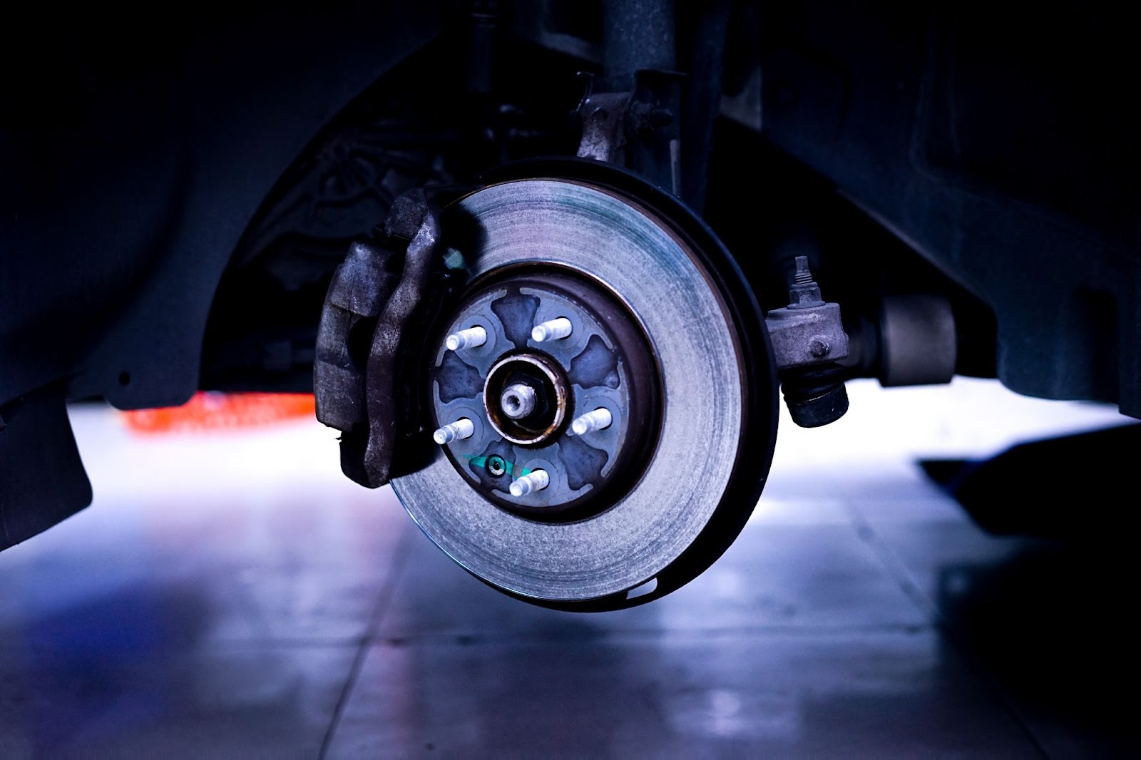
In disc brakes, brake pads clamp onto the rotating brake disc, converting the vehicle’s kinetic energy into thermal energy.
Friction Force:
Ff=μ×NF_f = \mu \times NFf=μ×N
Where:
- FfF_fFf: Friction force
- μ\muμ: Coefficient of friction (determined by pad and disc materials)
- NNN: Normal force applied by the caliper piston
Discs are often made from cast iron or carbon-ceramic composites, the latter offering superior heat resistance.
3.2 Drum Brakes: Circumferential Friction
Drum brakes use brake shoes to press against the inside of the drum, generating friction and slowing the vehicle. Drum brakes provide a larger contact surface, making them suitable for heavy loads.
4. Heat Management and Energy Dissipation
4.1 Kinetic Energy to Heat Energy
The vehicle’s kinetic energy is converted into heat energy during braking. Kinetic energy is calculated as:
Ek=12mv2E_k = \frac{1}{2} m v^2Ek=21mv2
Where:
- EkE_kEk: Kinetic energy
- mmm: Vehicle mass
- vvv: Vehicle speed
4.2 Heat Dissipation in Discs and Drums
Ventilated discs use internal channels to dissipate heat efficiently. Drums, while effective at handling heavy loads, may retain more heat, requiring periodic cooling. Modern designs incorporate high thermal conductivity materials to reduce thermal stress.
5. Dynamic Control and Safety Systems
5.1 Anti-Lock Braking System (ABS)
ABS prevents wheel lockup, maintaining steering control during braking.
How it Works:
- Wheel speed sensors monitor the rotational speed of each wheel.
- The ABS module modulates braking pressure to prevent skidding.
Friction Dynamics:
Maximum braking efficiency is achieved when the wheels rotate without slipping, leveraging the higher static friction coefficient over dynamic friction.
5.2 Electronic Braking Systems (EBS)
EBS electronically controls braking pressure, optimizing it based on load distribution and vehicle dynamics.
6. Braking Torque and Vehicle Dynamics
6.1 Braking Torque
Braking torque is the force that slows the wheels:
T=F×rT = F \times rT=F×r
Where:
- TTT: Braking torque
- FFF: Braking force
- rrr: Radius of the wheel
6.2 Stopping Distance
Stopping distance depends on vehicle speed, weight, and road conditions. It is calculated as:
d=v22μgd = \frac{v^2}{2 \mu g}d=2μgv2
Where:
- ddd: Stopping distance
- vvv: Vehicle speed
- μ\muμ: Coefficient of road friction
- ggg: Gravitational acceleration
7. Maintenance and Optimization
Hydraulic Systems
- Check hydraulic fluid levels regularly.
- Inspect for leaks in hoses and connections.
Air Systems
- Maintain air compressors and reservoirs.
- Drain water and oil from reservoirs periodically.
Brake Pads and Discs
- Monitor wear on pads and discs.
- Replace components showing excessive wear or damage.
Automev.Com Brake System Solutions
Automev.Com offers high-quality components for heavy-duty vehicle brake systems, including:
- Brake Discs and Drums
- Brake Cylinders and Pads
- Soon-to-Be-Added Air Compressors and Bellows
Visit our website to explore our range of products and ensure your vehicles operate with optimal safety and performance.
Automev.Com – Trusted Brake System Solutions for Heavy-Duty Vehicles

 TR
TR EN
EN

